
Introduction
In this eleventh installment of the VCF 9 Deployment series, we continue working with Virtual Private Cloud networking and focus on the second available architecture: Centralized Transit Gateway connectivity.
In the previous post, we created a VPC with Distributed Transit Gateway connectivity. This time, we will move to the Centralized Connectivity model, which provides additional networking capabilities such as NAT services, custom NAT rules, external IPs, and Layer 3 services through NSX Edge.
Centralized Connectivity is the preferred approach when workloads require more controlled north-south communication, advanced NAT behavior, and routing through dedicated NSX Edge nodes. It also gives us more flexibility when designing production-ready VPC environments where traffic flow, external access, and network services must be managed in a more predictable way.
If you didn’t see previous posts, go to:
VCF 9 Deployment PART1: Topology, ESX Host Preparation and VCF Installer deployment
VCF 9 Deployment PART2: VCF deployment
VCF 9 Deployment PART3: VCF Operation for Logs deployment.
VCF 9 Deployment PART4: VCF Single Sign-On configuration (Identity Broker and vCenter).
VCF 9 Deployment PART5: VCF Single Sign-On configuration (NSX Manager).
VCF 9 Deployment PART6: VCF Single Sign-On configuration (VCF Operations).
VCF 9 Deployment PART7: VCF Single Sign-On configuration (VCF Operations for Logs).
VCF 9 Deployment PART8: VCF Single Sign-On configuration (VCF Automation).
VCF 9 Deployment PART9: VCF Automation – Create VM App Organization and basic integrations.
VCF 9 Deployment PART10: Create VPC with Distributed Transit Gateway connectivity.
Create VPC and configure Centralized Connectivity
- Log into vCenter Server (https://vcf9-md01-vcenter01.blanketvm.com) -> switch to the
Networktab -> then click on the vCenter level in the left pane and choose theNetwork Connectivitytab.
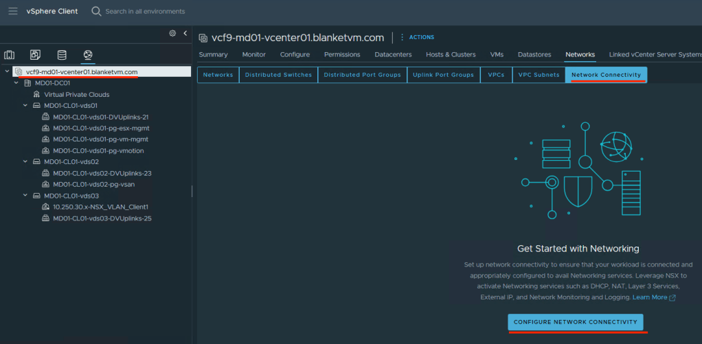
- Click
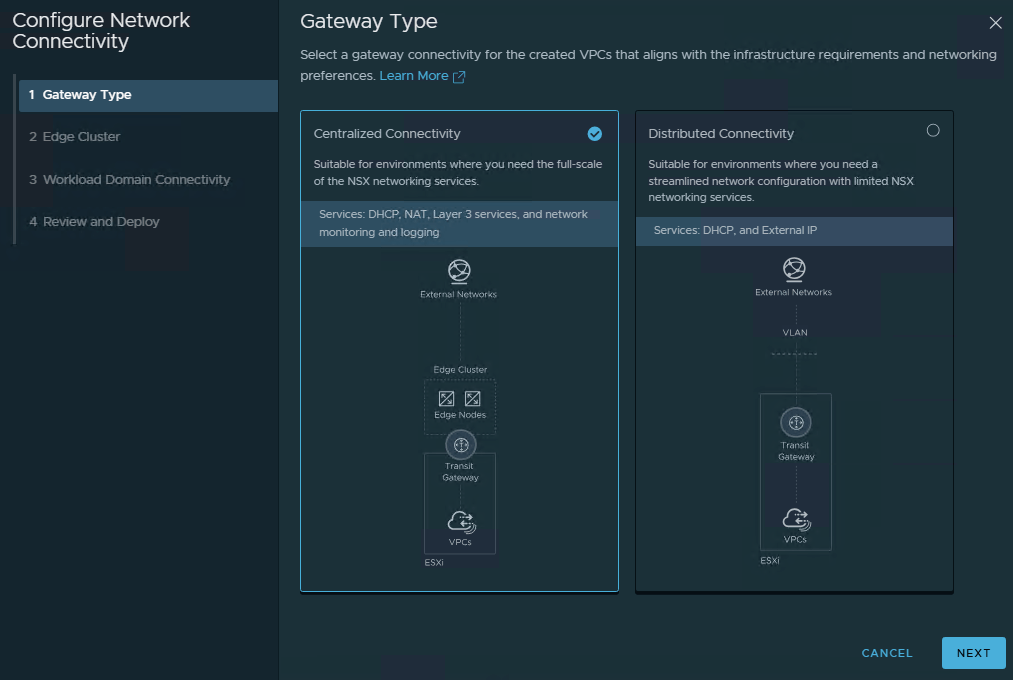
Configure Network Connectivity, choose theCentralized Connectivityoption, and clickNext.
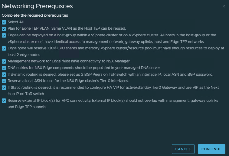
- Read and check all prerequisites. We need a VLAN for the BGP connection and the Edge TEP (in my case, 2511, 2512, and 2504). Click
Continue.
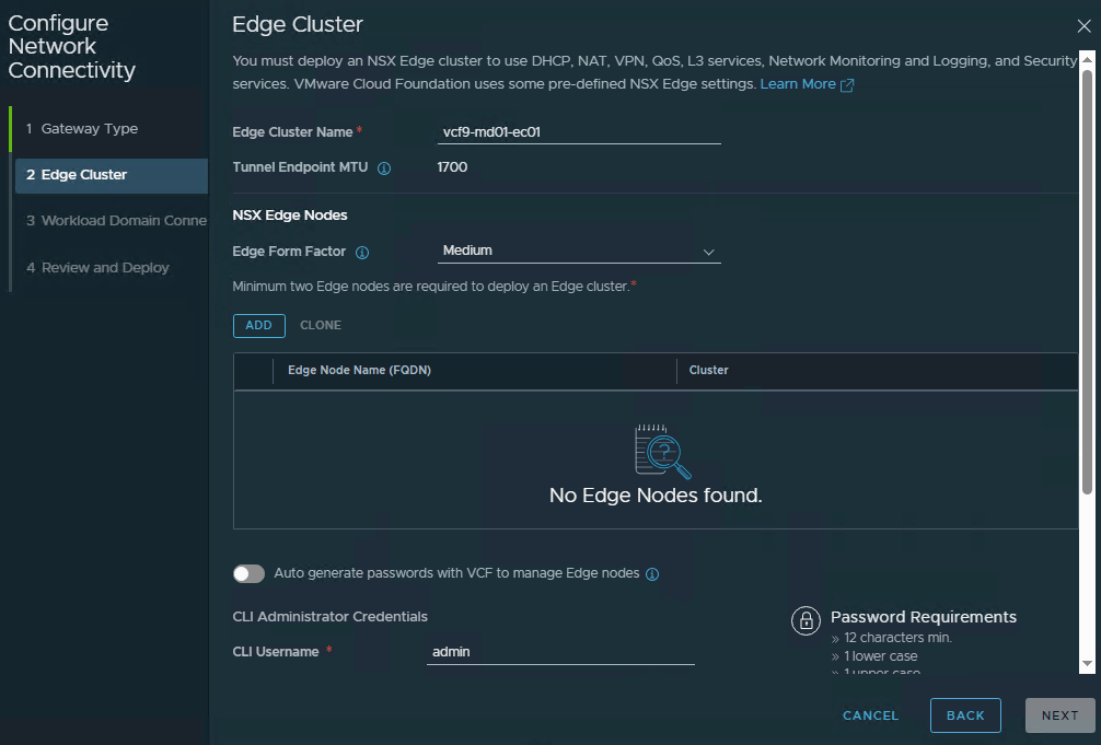
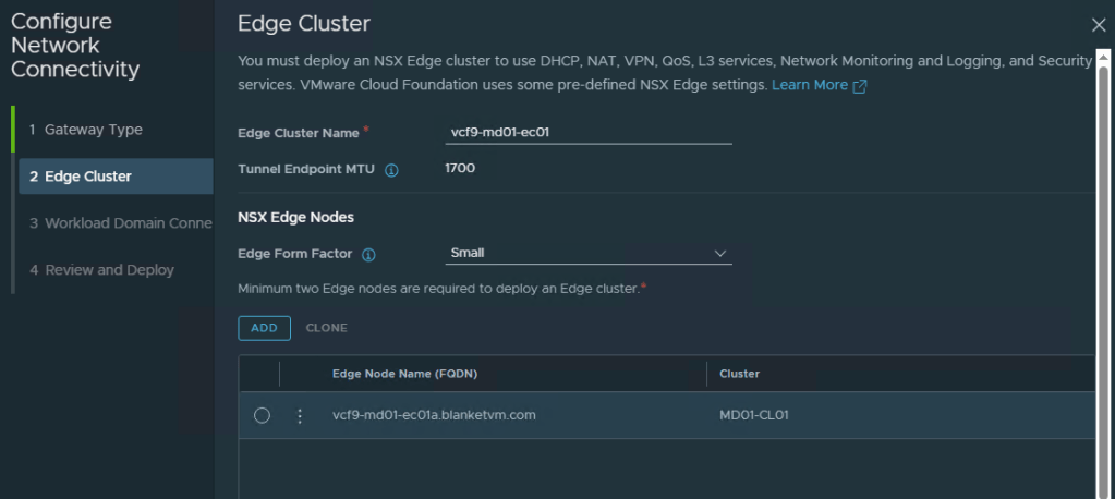
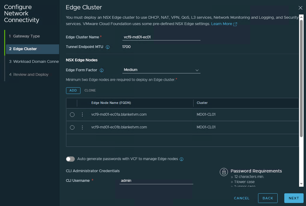
- Enter the required parameters for the Edge Cluster and click the Add button to add the first Edge node.
Edge Cluster Name: Name of the Edge cluster.
Edge Form Factor: Size of the Edge node. If you plan to use VKS, use a Large form factor.
Passwords: Passwords for admin, root, and audit users.
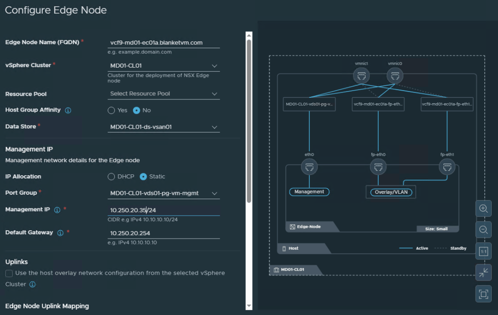
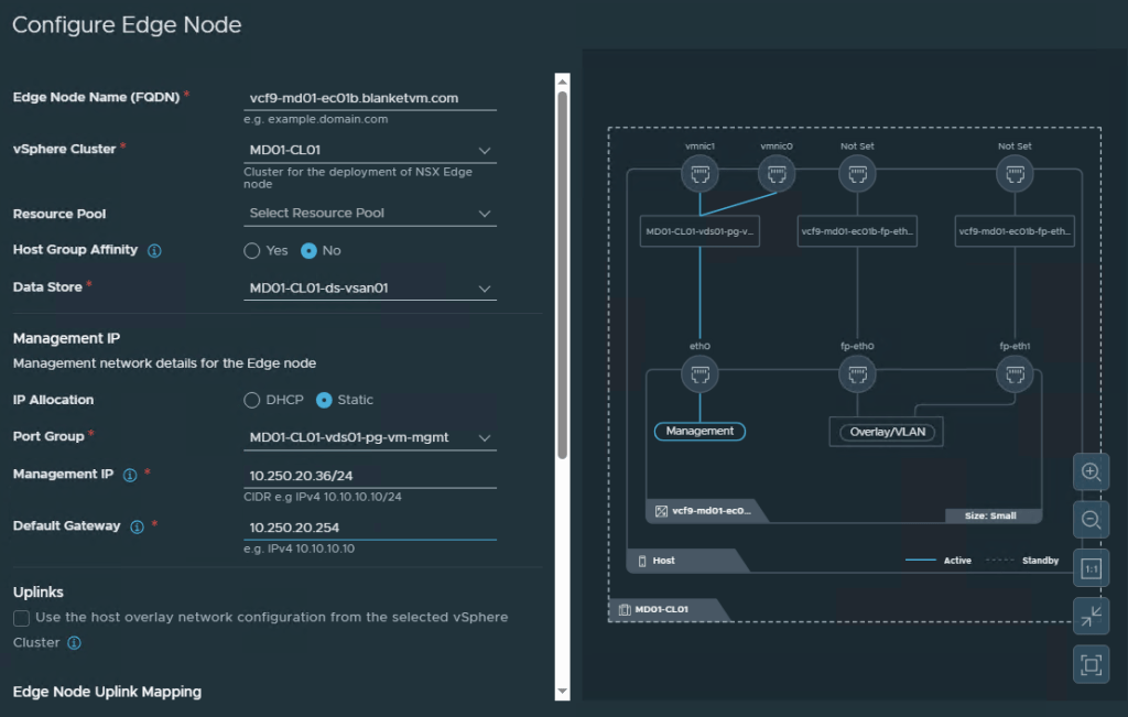
- Fill in the first Edge node configuration details:
Edge Node Name (FQDN): Defines the fully qualified domain name of the NSX Edge node. Must exist in DNS.
vSphere Cluster: Selects the vSphere cluster where the NSX Edge node will be deployed (Management Domain).
Resource Pool: Specifies the resource pool used for the Edge node deployment.
Host Group Affinity: Determines whether the Edge node should be deployed using a specific host group affinity rule.
Data Store: Selects the datastore where the Edge node virtual machine files will be stored.
IP Allocation: Defines whether the Edge node management IP address is assigned using DHCP or configured statically (I have no DHCP, so I will use static assignment).
Port Group: Selects the management network port group used by the Edge node.
Management IP: Assigns the management IP address and subnet prefix to the Edge node.
Default Gateway: Defines the gateway used by the Edge node management network.
Uplinks: Controls whether the Edge node uses the host overlay network configuration from the selected vSphere cluster. I will make my own configuration.
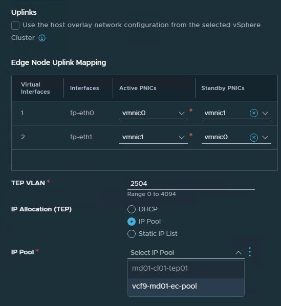
Continue with the next part:
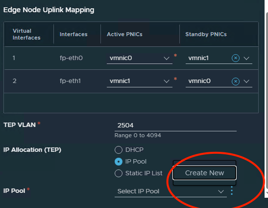
Virtual Interfaces: Represents the Edge node uplink interface number used for external or transport connectivity.
Interfaces: Shows the Edge node interface name, such as fp-eth0 or fp-eth1.
Active PNICs: Defines the physical NIC used as the active uplink for that Edge interface.
Standby PNICs: Defines the backup physical NIC used if the active uplink fails.
We need to also define the TEP VLAN for Edge communication and how TEP IPs will be allocated.
TEP VLAN: Defines the VLAN used for the Edge Transport Endpoint traffic; in this example, VLAN 2504 is used.
IP Allocation (TEP): Defines how the Edge TEP IP addresses will be assigned.
DHCP: Automatically assigns the Edge TEP IP address from a DHCP server.
IP Pool: Assigns the Edge TEP IP address from a predefined NSX IP pool.
Static IP List: Allows manual assignment of specific TEP IP addresses.
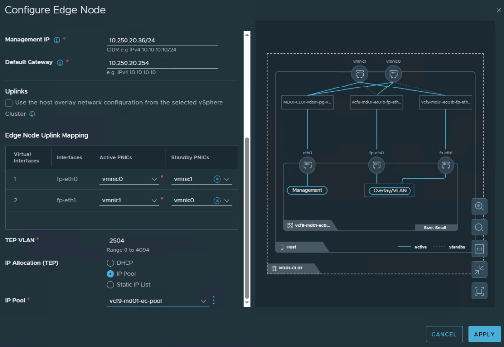
IP Pool: Selects the IP pool that will provide TEP IP addresses for the Edge node.
In my example, I will create a new IP Pool for Edge TEP. Click Create New next to the IP Allocation part.
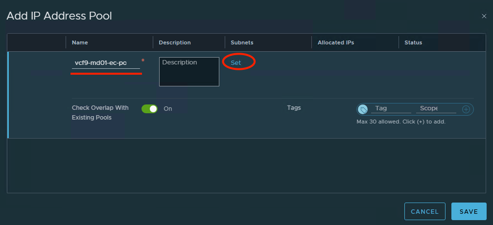
Put the name of the IP Pool and set the Subnets to define IP Ranges for the new pool.
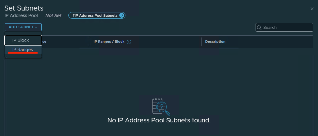
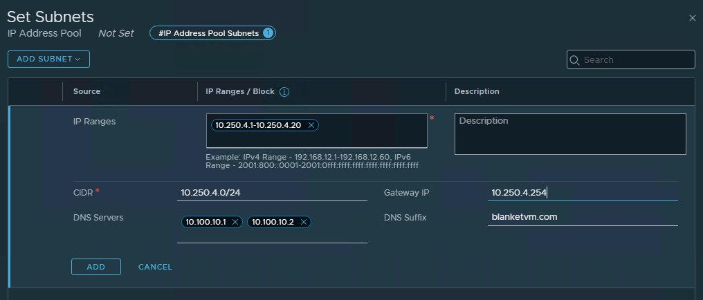
Click Add and Apply.
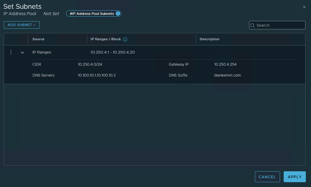
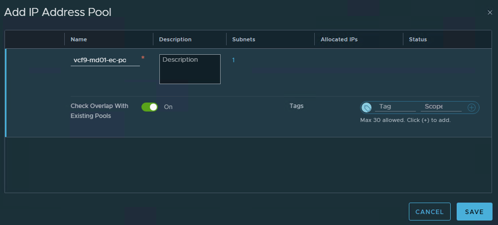
Then Save.
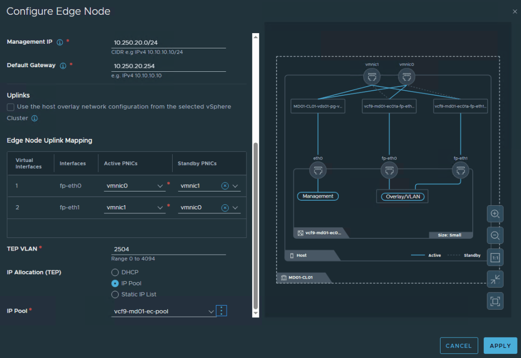
- Now let’s create a second Edge node. I will not explain the same fields the second time, so everything you have got on screenshots.
- Now we go to Workload Domain Connectivity and configure BGP connectivity for our Edge nodes.
I did not mention it at the beginning, but we need physical ToR switches or routers configured for BGP connectivity. Below, you can find my VyS configuration.[edit]secret12
vyos@vyos# set protocols bgp neighbor 10.250.11.1 address-family ipv4-unicast
[edit]
vyos@vyos# set protocols bgp neighbor 10.250.11.1 remote-as 54545
[edit]
vyos@vyos# set protocols bgp neighbor 10.250.11.1 password3
[edit]
vyos@vyos# set protocols bgp neighbor 10.250.11.2 address-family ipv4-unicast
[edit]
vyos@vyos# set protocols bgp neighbor 10.250.11.2 remote-as 54545
[edit]
vyos@vyos# set protocols bgp neighbor 10.250.11.2passwordsecret123
[edit]
vyos@vyos# set protocols bgp neighbor 10.250.12.1 address-family ipv4-unicast
[edit]
vyos@vyos# set protocols bgp neighbor 10.250.12.1 remote-as 54545
[edit]
vyos@vyos# set protocols bgp neighbor 10.250.12.1passwordsecret123
[edit]
vyos@vyos# set protocols bgp neighbor 10.250.12.2 address-family ipv4-unicast
[edit]
vyos@vyos# set protocols bgp neighbor 10.250.12.2 remote-as 54545
[edit]
vyos@vyos# set protocols bgp neighbor 10.250.12.2passwordsecret123
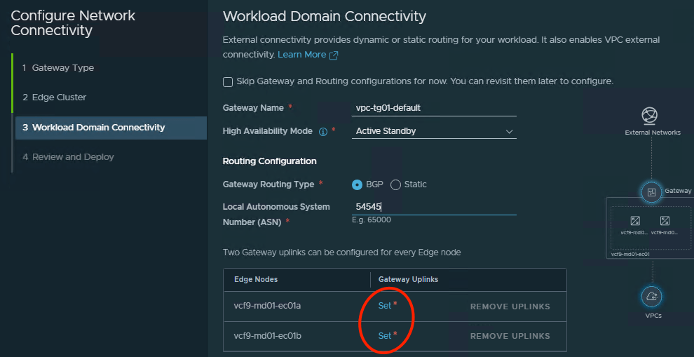
Gateway Name: Specifies the name of the Tier-0 gateway that provides external connectivity for the workload domain.
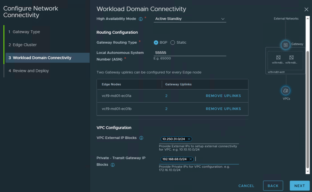
High Availability Mode: Specifies the HA mode for the gateway; in this example, Active-Standby is selected to provide redundancy.
Gateway Routing Type: Selects the routing method used by the Tier-0 gateway.
Local Autonomous System Number (ASN): Defines the local BGP ASN used by the Tier-0 gateway; in this example, ASN 54545 is used.
Edge Nodes: Show the NSX Edge nodes that will host the gateway uplinks.
Gateway Uplinks: Defines the uplink interfaces that each Edge node uses to connect the Tier-0 gateway to the external network.
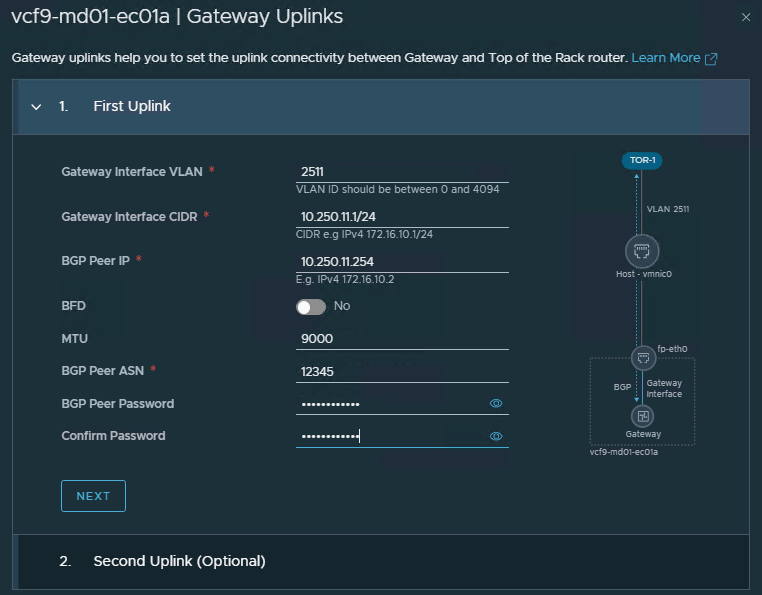
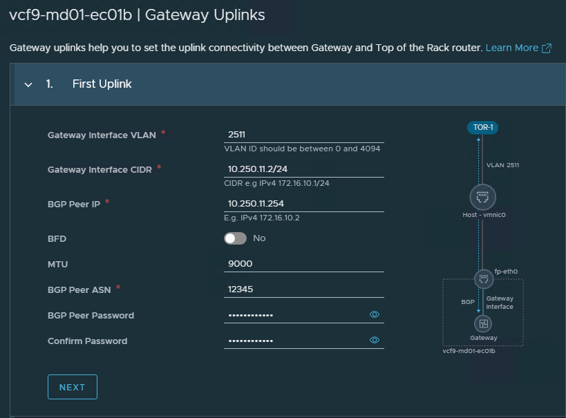
Click Set next to the first Edge node and configure the first interface.
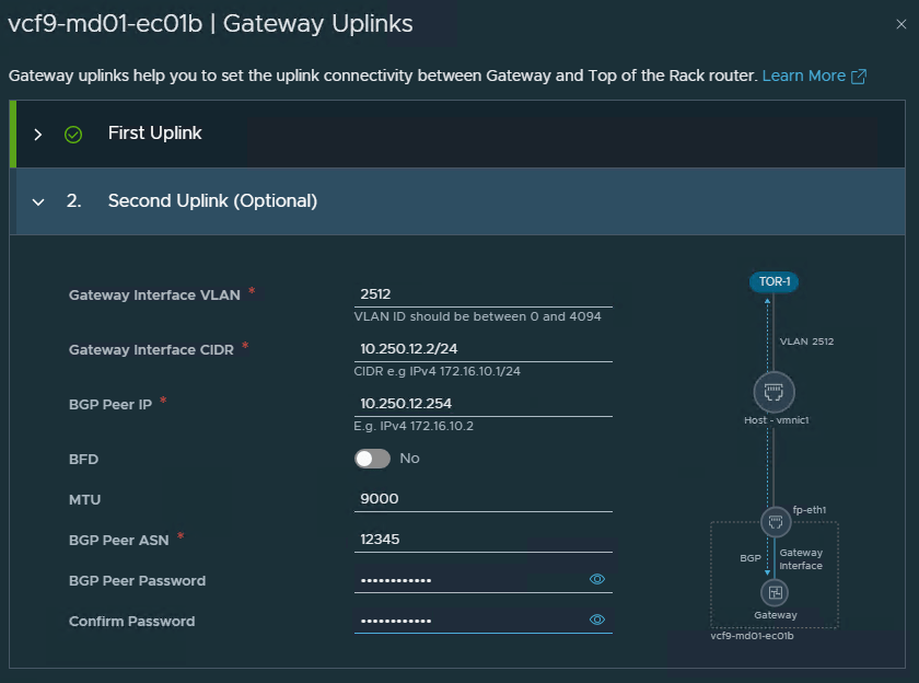
Gateway Interface VLAN: Defines the VLAN used for the Tier-0 gateway uplink interface; in this example, VLAN 2511 is used.
Gateway Interface CIDR: Assigns the IP address and subnet prefix to the gateway uplink interface; here it is 10.250.11.1/24.
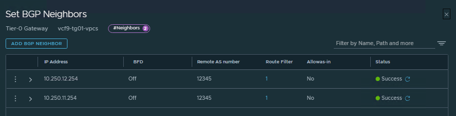
BGP Peer IP: Defines the IP address of the upstream router BGP neighbor; in this example, the peer IP is 10.250.11.254.
BFD: Enables or disables Bidirectional Forwarding Detection for faster failure detection between the gateway and the BGP peer.
MTU: Defines the maximum transmission unit for the gateway uplink interface; here it is set to 9000.
BGP Peer ASN: Defines the Autonomous System Number of the upstream BGP router; in this example, ASN 12345 is used.
BGP Peer Password: Sets the BGP authentication password used between the Tier-0 gateway and the peer router.
Now configure the second interface for the first Edge node.
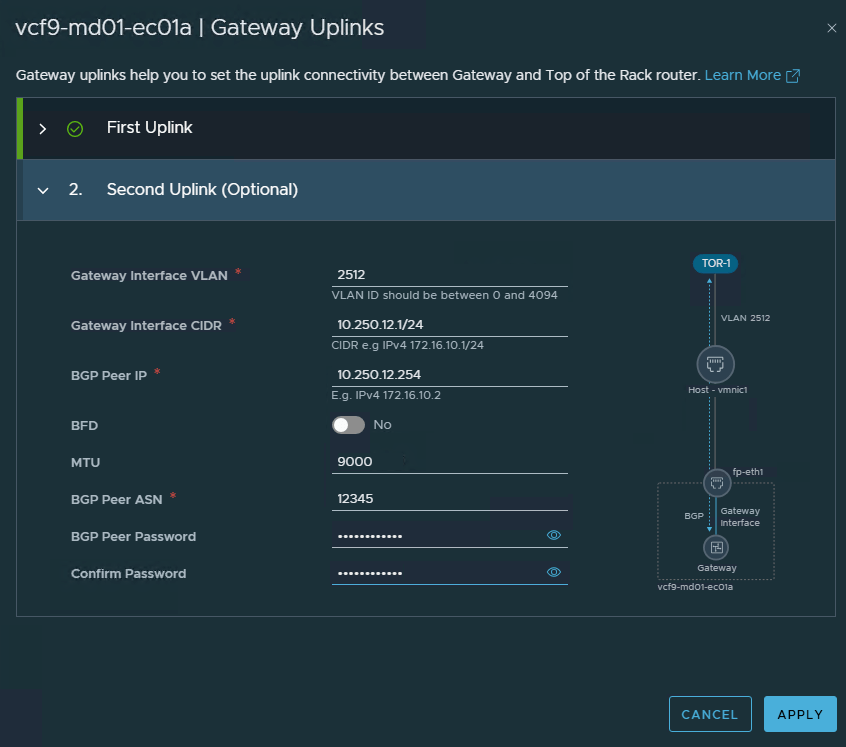
Then go to the second node and configure two interfaces.
- In this step, we will finalize Edge configuration by providing:
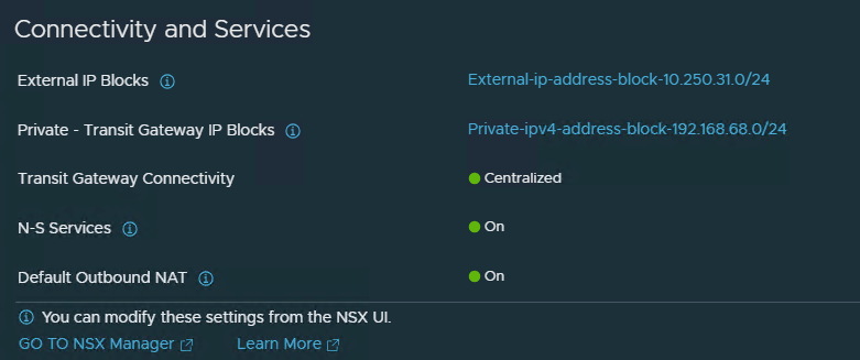
VPC External IP Blocks: Defines the external IP range used by the VPC for north-south connectivity, such as NAT or external access; in this example, 10.250.31.0/24 is used.
Private – Transit Gateway IP Blocks: Defines the private IP range used internally for VPC Transit Gateway connectivity; in this example, 192.168.68.0/24 is used.
External IPs: These IPs are consumed when workloads inside the VPC need external connectivity through centralized services.
Private IPs: These IPs are used for internal VPC gateway communication and should not overlap with existing network ranges.
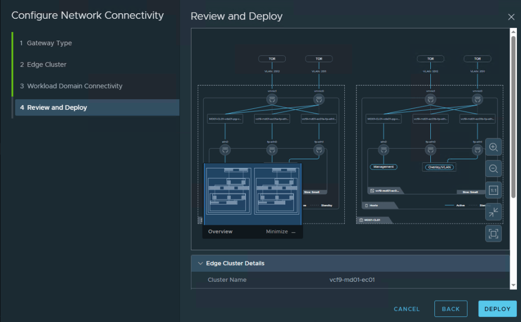
- Review topology and click
Deploy.
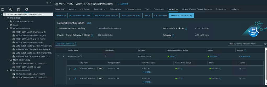
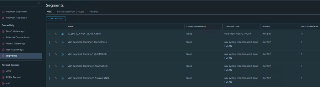
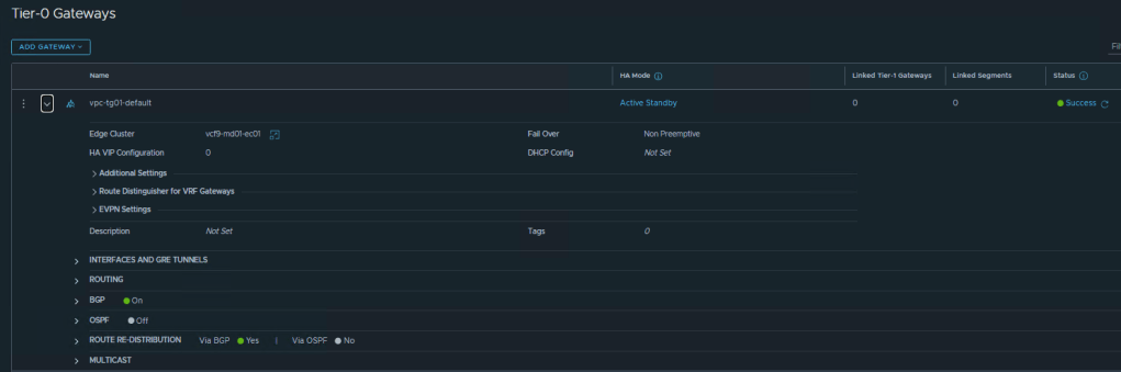
- Below are a few screenshots showing the final configuration after the Edge cluster deployment.
Network Connectivity from vCenter:
NSX Segments:
Tier-0 BGP Configuration:

- Now, let’s create a VPC and connect VMs to it
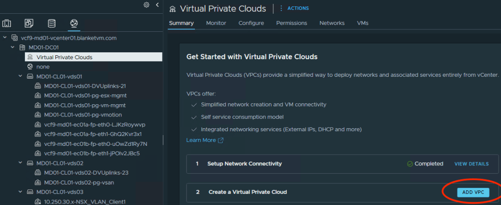
Go toVirtual Private Cloudsand clickAdd VPC.
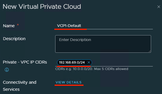
Provide a name and Private VPC IPs.
Click View Details to check the Centralized Connectivity configuration.
Save.
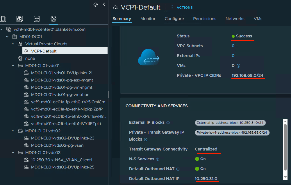
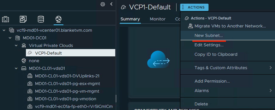
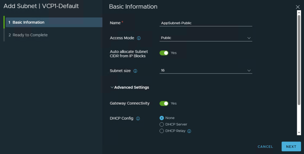
- Create two subnets in our VPC.
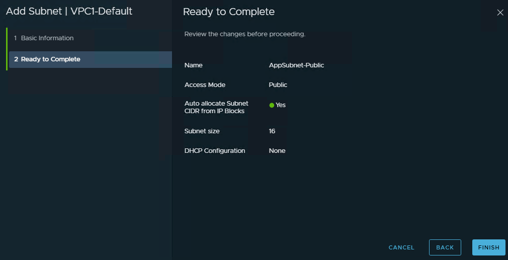
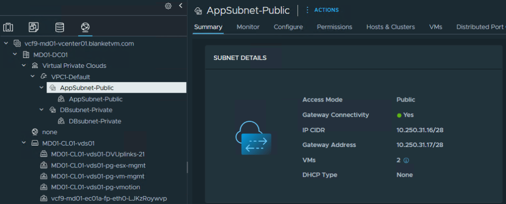
AppSubnet and DB Subnet.
AppSubnet will use Public Access Mode and will have IPs assigned from the External IP range.
DBSubnet will use Private VPC IPs.
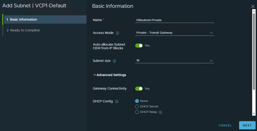
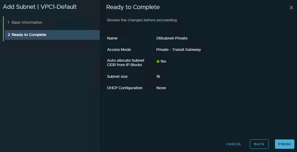
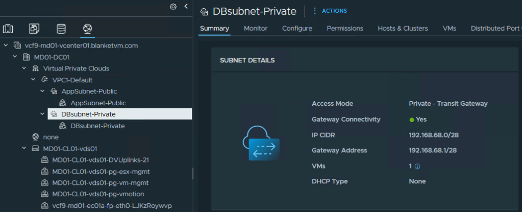
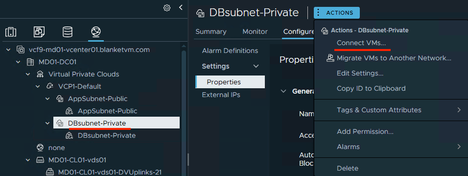
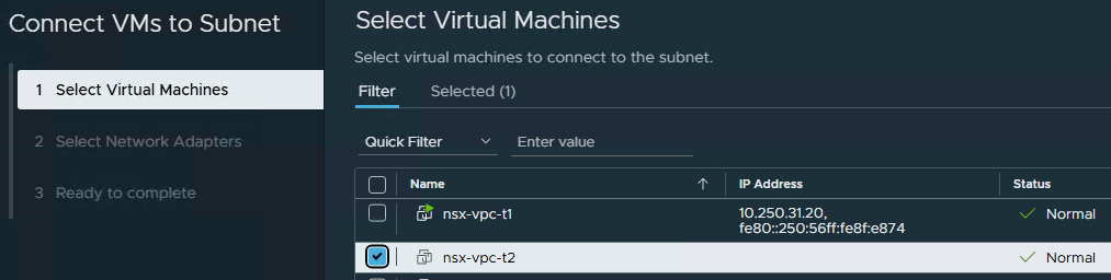
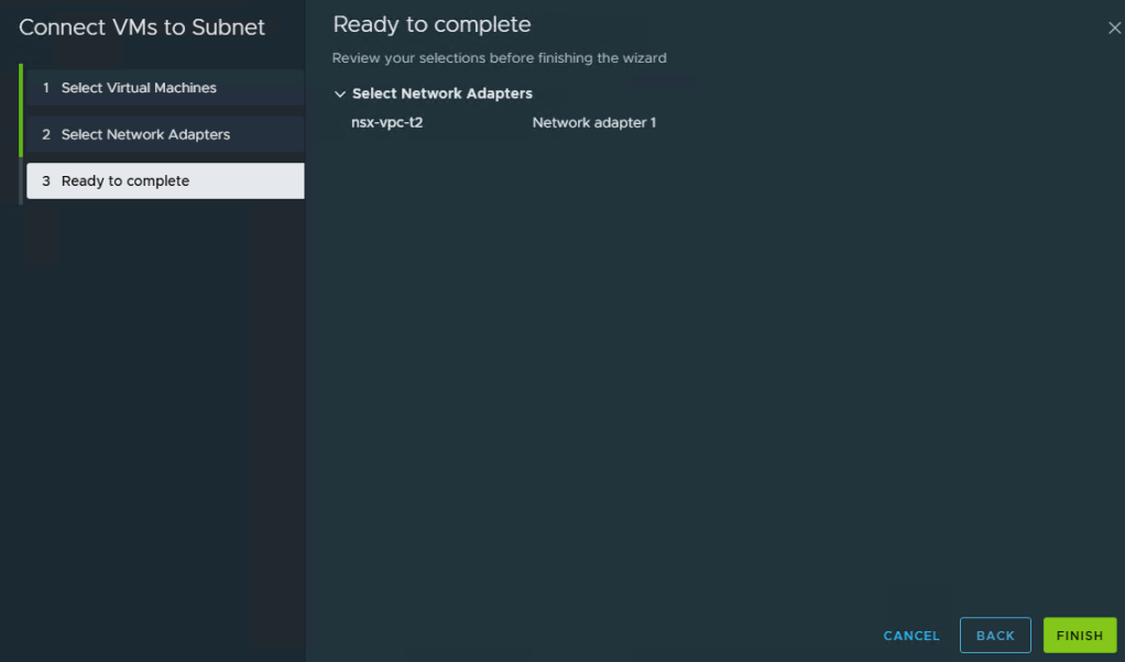
- Let’s connect test VMs to our subnets.
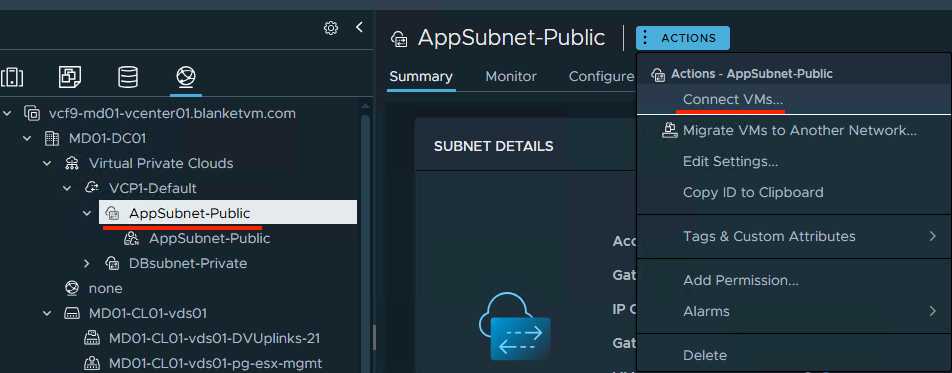
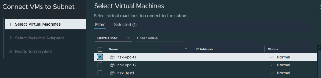
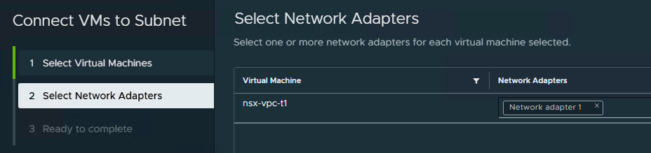
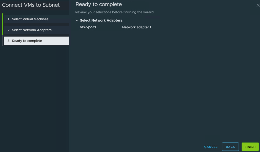
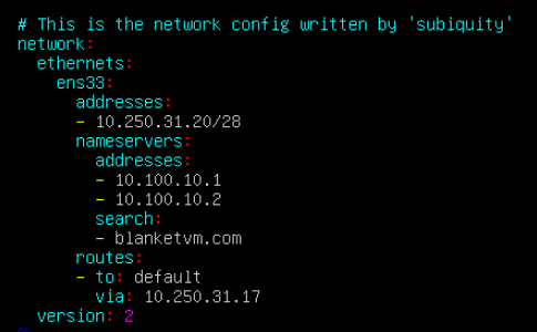
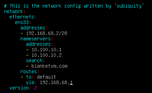
And the second VM to the DBSubnet network.

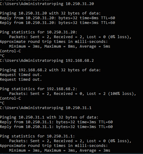
- Now we can check the connectivity between VMs and the outside network.
As you can see VM connected to the DBsubnet does not have external connectivity,
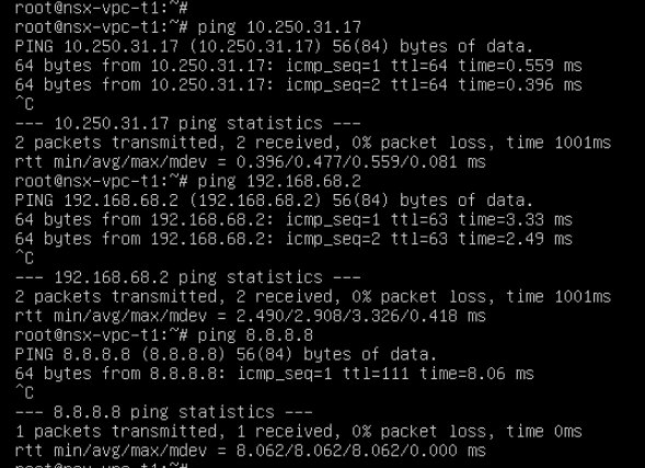
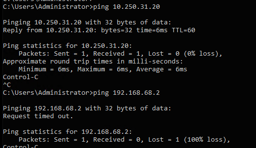
Let’s fix it by assigning an IP from the external range (NAT).
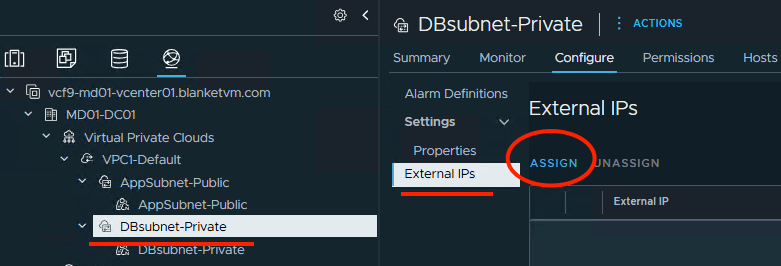
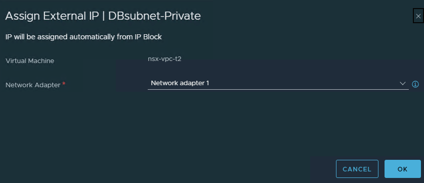

Now works!
Conclusion:
In PART 11, we moved from Distributed Transit Gateway connectivity to the Centralized Connectivity model in VCF 9. You deployed and configured the required NSX Edge nodes, created the Edge TEP IP pool, configured the Tier-0 gateway with BGP routing, mapped gateway uplinks to the Edge nodes, and prepared the required VPC external and private Transit Gateway IP blocks.
With Centralized Connectivity in place, the VPC can now consume advanced network services such as NAT, external IP assignment, and controlled north-south routing through NSX Edge. This design provides greater flexibility and better control over production workloads that require centralized traffic flow and external connectivity.
Stay tuned!
 BlanketVM