
Introduction
In this tenth installment of the VCF 9 Deployment series, we move beyond the core management domain setup into a key piece of network architecture. VCF 9 allows us to configure two main architectures regarding VPC:
- Centralized Connectivity – the best approach when you need all features like: NAT services, Layer 3 services.
- Distributed Connectivity – suitable for environments where you need streamlined network configuration with limited NSX services.
The differences between Centralized and Distributed services:
| Capability | Distributed Connectivity | Centralized Connectivity (Active/Standby) | Centralized Connectivity (Active/Active) |
|---|---|---|---|
| VPC Auto-NAT | No | Yes | No |
| External IPs | Yes | Yes | Yes |
| Custom NAT rules on VPC | No | Yes | Yes |
| Transit Gateway (DNAT/SNAT) | No | Yes | No |
| Transit Gateway (Reflexive NAT) | No | Yes | Yes |
| NSX Edge Required | No | Yes | Yes |
| VCF Automation Supervisor Support | No | Yes | No |
| VM Mobility across physical L3 Boundaries | No | Yes | No |
Today, we will keep focus on a VMware Cloud Foundation 9 (VCF 9) Virtual Private Cloud (VPC) with Distributed Transit Gateway (DTGW) connectivity. A distributed connection is one where a Transit Gateway connects directly to a VLAN provisioned in the fabric without the need to deploy Edge nodes or configure dynamic routing.
In this post, we’ll walk through the process of creating a VPC within VCF 9, integrating it with a DTGW, and ensuring proper connectivity between network domains.
If you didn’t see previous posts, go to:
VCF 9 Deployment PART1: Topology, ESX Host Preparation and VCF Installer deployment
VCF 9 Deployment PART2: VCF deployment
VCF 9 Deployment PART3: VCF Operation for Logs deployment.
VCF 9 Deployment PART4: VCF Single Sign-On configuration (Identity Broker and vCenter).
VCF 9 Deployment PART5: VCF Single Sign-On configuration (NSX Manager).
VCF 9 Deployment PART6: VCF Single Sign-On configuration (VCF Operations).
VCF 9 Deployment PART7: VCF Single Sign-On configuration (VCF Operations for Logs).
VCF 9 Deployment PART8: VCF Single Sign-On configuration (VCF Automation).
VCF 9 Deployment PART9: VCF Automation – Create VM App Organization and basic integrations.
Network Architecture
First, let’s take a look at our target architecture and configuration.
Subnets/IPs:
– 10.250.31.0/24 (VLAN: 2531) – VLAN used for external connectivity. VLAN 2531 is configured as any other VLAN in the vSphere infrastructure that we usually use for Port Groups and VM connectivity. You must have such a VLAN configured in the environment.
– 10.250.31.254 – Upstream router interface. Gateway for VLAN 2531.
– 100.64.0.0/31 – Internal subnet between Transit Gateway and VPC Gateway. It is created automatically during configuration.
– 10.250.31.32/27 – One of the VPC subnets created from the External IP Block. Do not create manually.
– 10.250.31.33 – Default Gateway for subnet above.
– 192.168.68.0/24 – Private Transit Gateway IP Block. From that block, we will create smaller subnets for Virtual Machines. It allows connectivity between VPCs connected to the same Transit Gateway.
– 192.168.68.0/28 – One of the smaller subnets created from larger block.
– 192.168.68.1 – Default Gateway for subnet mentioned above.
– 192.168.100.0/22 – Internal IP Block for Private VPC subnets. The same IPs can be used inside each VPC. It is unique only inside VPC.
Create a VPC and configure Distributed Connectivity
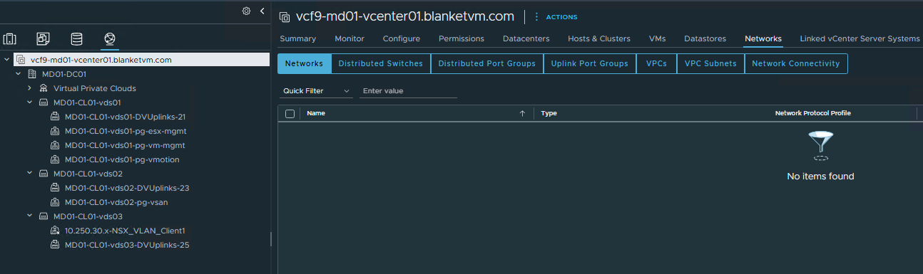
- Log into vCenter Server (https://vcf9-md01-vcenter01.blanketvm.com) -> switch to
Networktab -> then click on vCenter level in the left pane and chooseNetwork Connectivitytab.

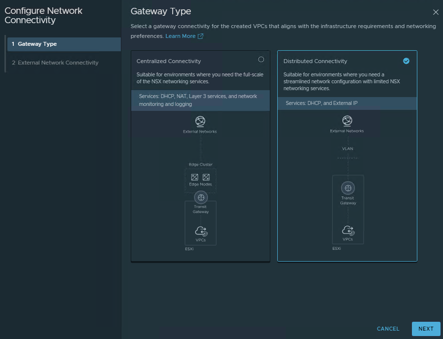
- Choose the
Distributed Connectivityoption and clickNext.
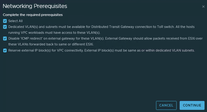
- Read and check all prerequisites. We need a VLAN (in my case, 2531) and ICMP redirect disabled on the external gateway for VLAN 2531.
ClickContinue.
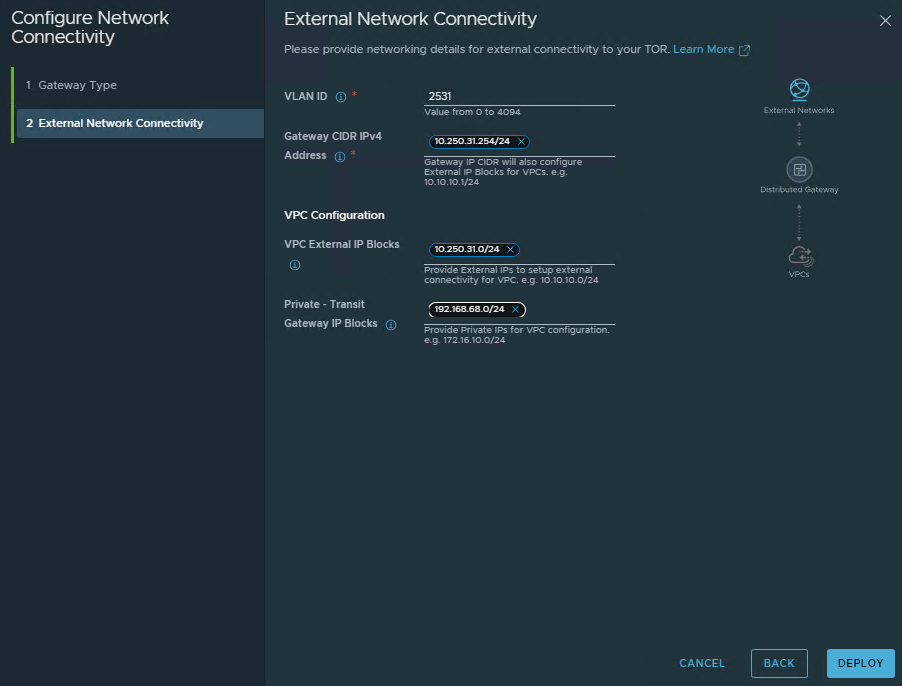
- Fill
External Connectivitynetwork details:
VLAN ID: This VLAN is dedicated to the external connectivity of workloads inside VPCs and must be stretched across all clusters where VPCs are deployed. 2531 in my case.
Gateway CIDR IPv4 Address: The gateway address through which the traffic should be routed to the external network.
VPC External IP Block: IP Block used for that VPC. Must be a part of VLAN 2531.
Private – TGW IPV4 Blocks: The private transit gateway IP Block for communication across VPCs. Usually, a network mask with 24bits is too small. Probably for the production environment, you will use a larger subnet.
ClickDeploy.
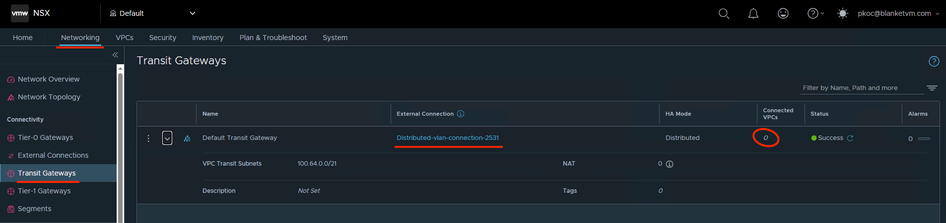
- From the
NSX UIperspective, we can confirm that we see theTransit Gatewayobject. Currently, we have no VPC connected, but we plan to do that in the next steps.
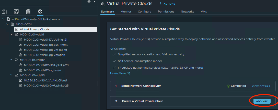
- Go back to the
vCenter Server UI. On theNetwork tab-> selectVirtual Private Cloudson the left pane -> clickAdd VPCon the right side.
- Fill the VPC Details
Name: VPC name.
Private – VPC IP CIDRs: IP CIDRs that can be assigned to private subnets of this VPC. These CIDRs are local to VPCs and can overlap between the VPCs.
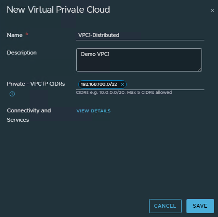
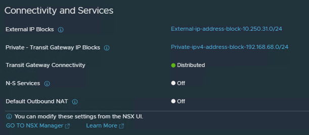
Click on View Details next to Connectivity and Services and check which are enabled by default.
Create subnets inside VPC
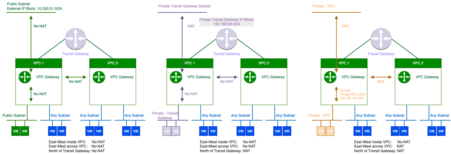
Before we create a subnet, let’s talk about possible types of subnets and the differences between them.
We have 3 subnet types in the VPC:
- Private – VPC
The subnet is only accessible from within the VPC. - Private – Transit Gateway
The subnet is accessible from VPCs within Virtual Private Clouds, but it is not advertised beyond the Transit Gateway that connects to the external datacenter network. - Public
The subnet is accessible from the external datacenter network.
Communication between subnets:
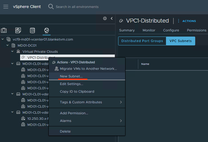
- To create the first subnet, go to:
vCenter UI -> Networking tab -> Select VPC on the left pane -> right click and choose New Subnet.
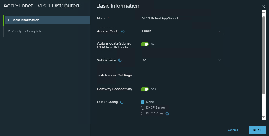
- Fill in
Basic Informationabout subnet:
Name: The name of the subnet.
Access Mode: Select Public (modes described above)
Auto-allocate Subnet CIDR from IP Blocks: Enable if you want to let VMware automatically assign subnets or do it manually.
Gateway Connectivity: Enabled
DHCP Config: None (or you can choose to assign IPs through DHCP).
ClickNext.
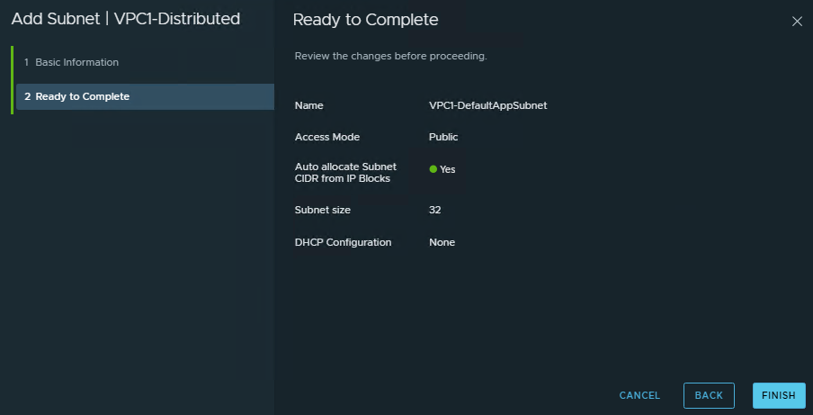
- Review the summary and click
Finish.
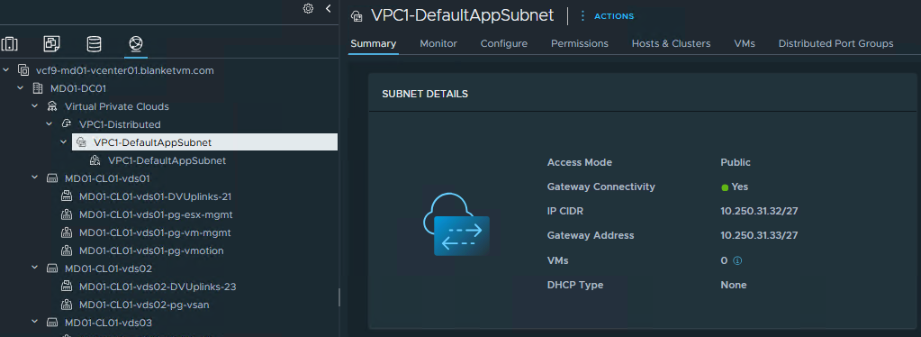
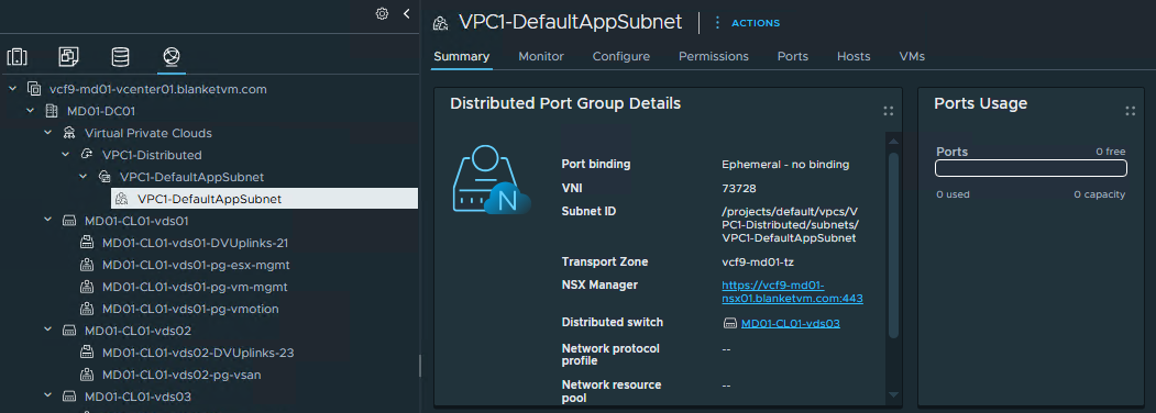
- From the vCenter UI, we can see that a new subnet has been created. Please review the subnet details if you have chosen Auto-allocate mode and note subnet details like mask, gateway, etc.
- Repeat steps 1-4 and create the second subnet, but this time
Access Mode = Private - Transit Gateway(I have only one VPC, so we will not test Private VPC subnets).


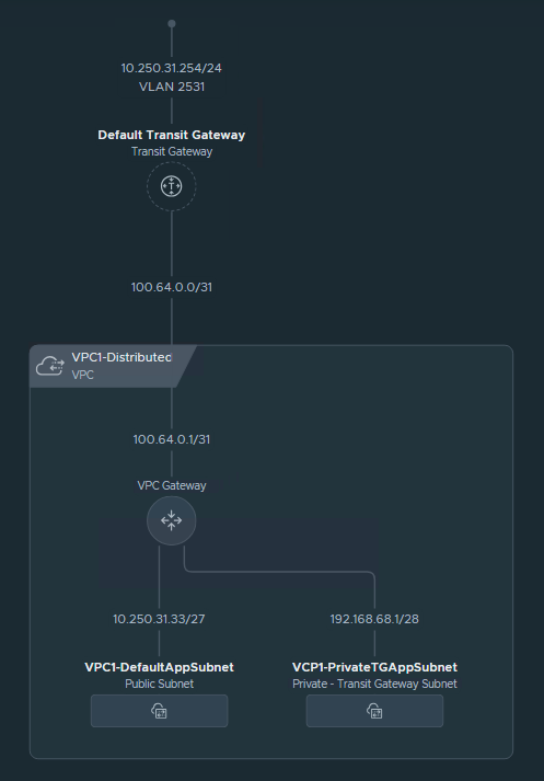
- Note the new subnet details. Take a look, this time we created a subnet from the 192.168.68.0/24 IP block.
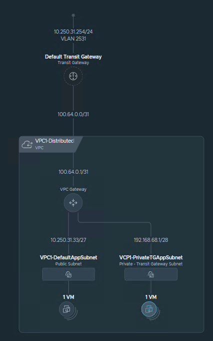
Below, you can see the current network topology.
Connect Virtual Machines to VPC and test connectivity
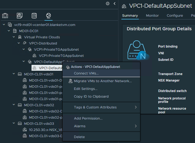
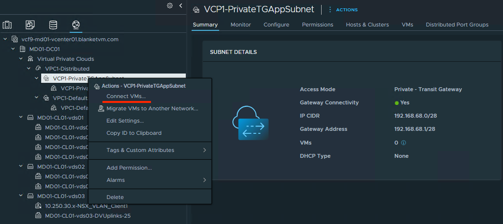
- Go to
vCenter UI -> Networking tab-> select the newly created subnet and right-click on its name.
SelectConnect VMs...
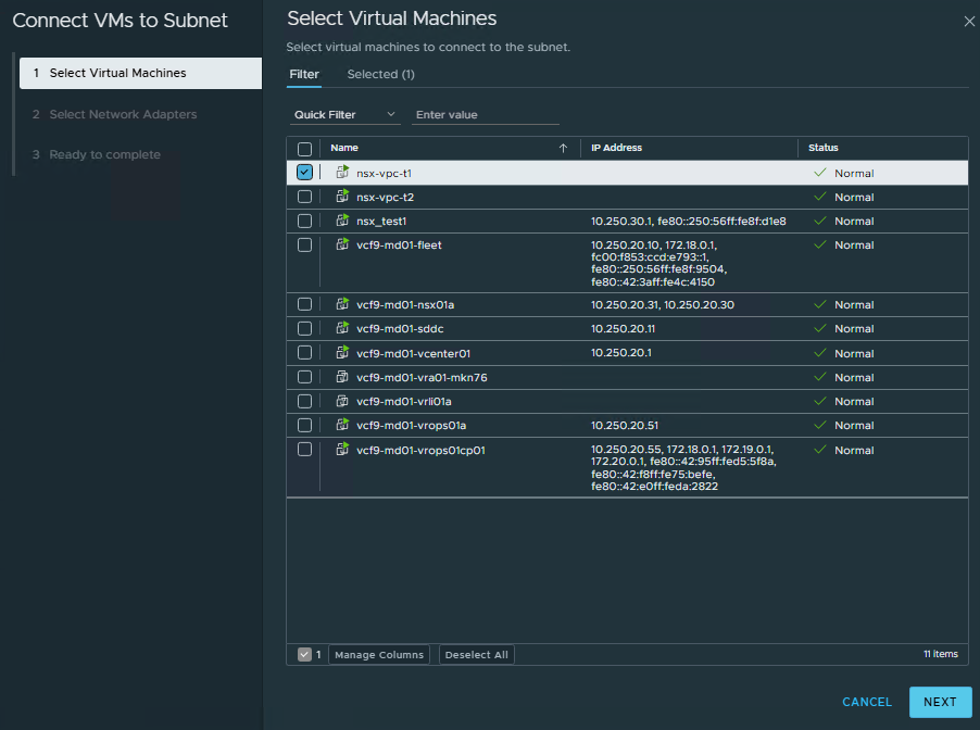
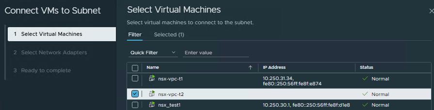
- Select VM/VMs that you want to connect to the subnet and click
Next.
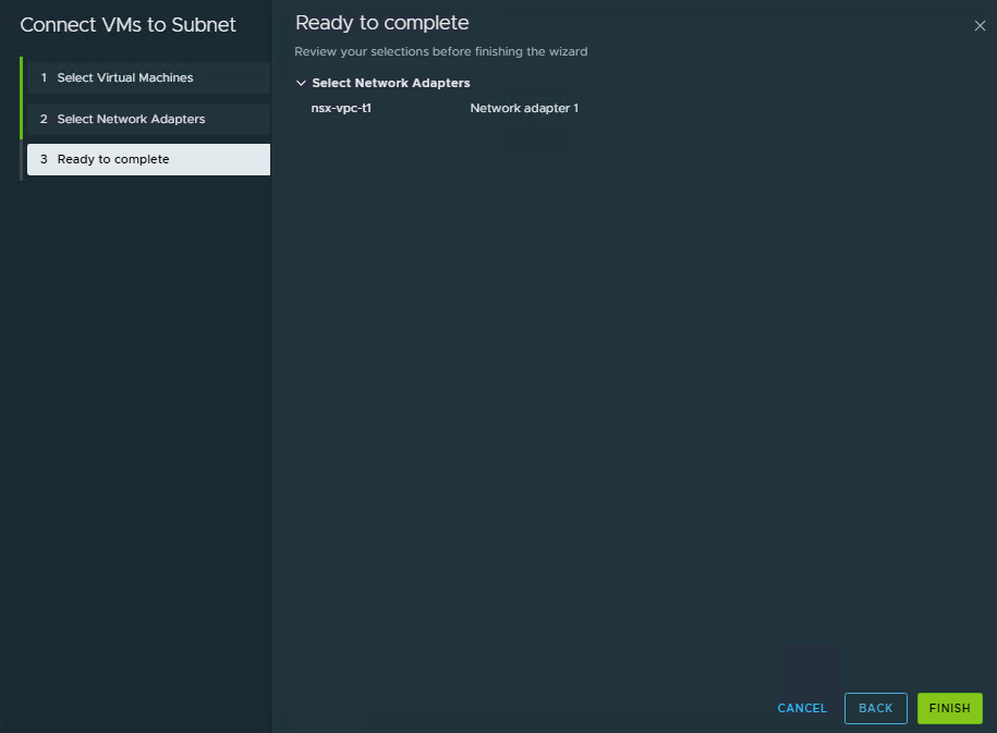
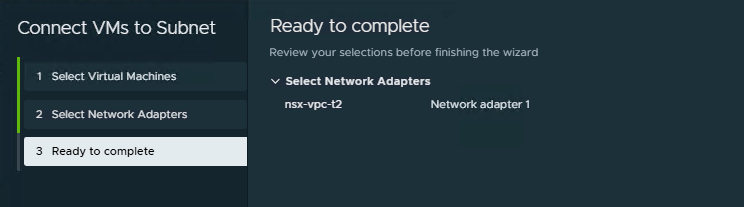
- Select Network Adapter, then click
NextandFinish.

- My test virtual machines are Ubuntu-based, and I need to assign a static IP address to my VM. I have chosen 10.250.31.34 (I am connecting this VM to the public subnet).
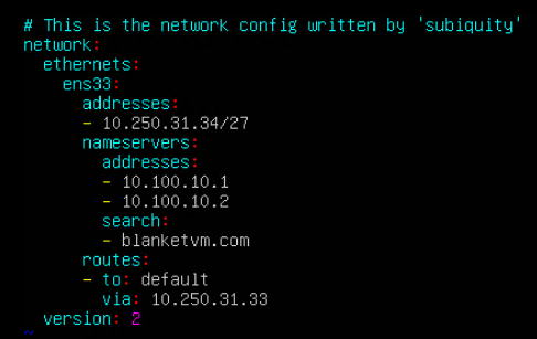
From the NSX UI, we can see the IP assigned to the VM and the updated Network Topology.


- Test connectivity using Ping.
– VM1 (Public) -> Gateway: PASS
– VM1 (Public) -> Internet: PASS
– Workstation -> VM1 (Public): PASS

- Connect the second test virtual machine to the second test subnet. This time,
Private - Transit Gatewaysubnet.
- Select Network Adapter, then click
NextandFinish.
- Assign an IP Address from the second subnet to the virtual machine and configure it on the OS. Take a look, this time we have an IP from the private subnet.

From the NSX UI, we can see the IP assigned to the VM and the updated Network Topology.

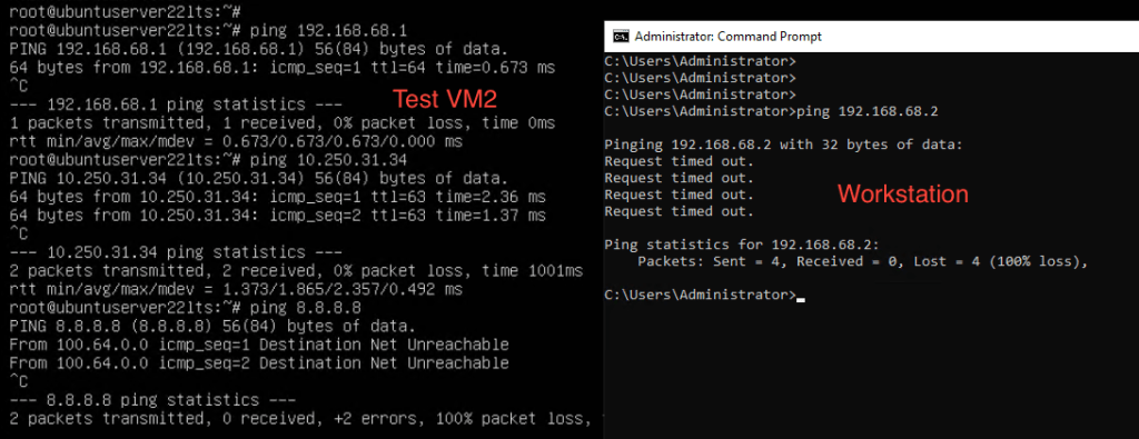
- Test connectivity using Ping.
– VM2 (Private) -> Gateway: PASS
– VM2 (Private) -> Internet: FAILED
– Workstation -> VM2 (Private): FAILED
– VM2 (Private) -> VM1 (Public): PASS
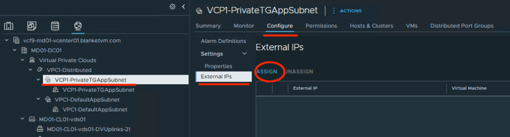
- To have external communication. We have to assign a Public IP to the second virtual machine.
To do that, go to: vCenter UI -> Networking tab -> Select your private subnet on the left pane -> Configure tab -> External IPs -> Assign.
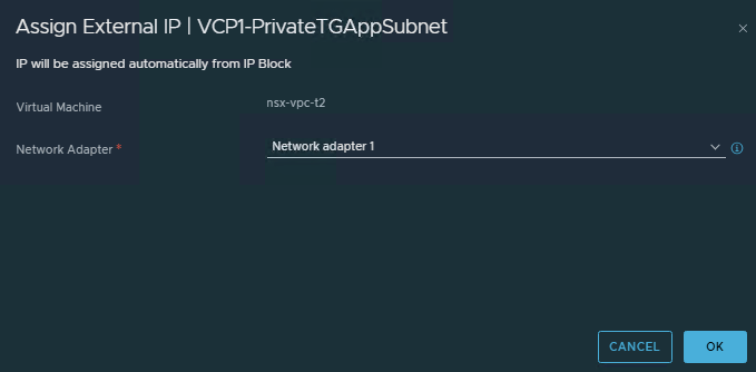
- Select the Network Adapter that you want to assign a Public IP (create NAT). And click
OK.
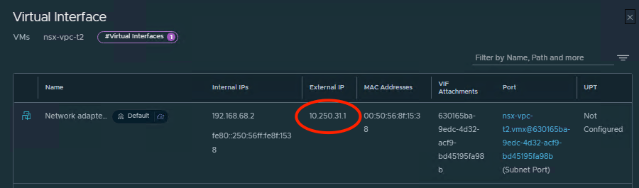
- You can see in vCenter UI that a new Public IP is assigned.

From the NSX UI, we can see an External IP address assigned to the VM.
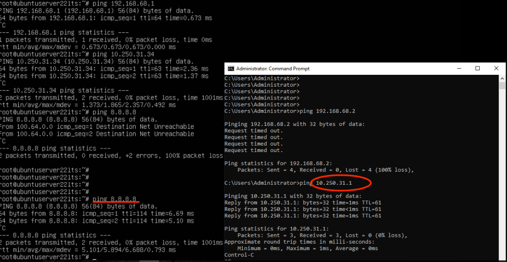
- Test connectivity using Ping.
– VM2 (Private) -> Gateway: PASS
– VM2 (Private) -> Internet: PASS
– Workstation -> VM2 (Private): PASS
– VM2 (Private) -> VM1 (Public): PASS
Conclusion:
In PART 10, we took VCF 9 from “VPCs on paper” to a working VPC with Distributed Transit Gateway (DTGW) connectivity. You built the VPC, chose the right subnet type (Public, Private–Transit Gateway, or Private–VPC), attached it to the DTGW, and validated east–west and north–south flows with the correct NAT behavior and route advertisements.
In the next post, we will configure Centralized Connectivity.
Stay tuned!
