
Introduction:
Welcome to the second post in my new blog series on VMware Cloud Foundation (VCF) 9 Deployment. In this multi-part guide, I’ll walk you step by step through the whole installation process of VCF 9 – from initial planning and environment preparation to a fully functional private cloud stack built on VMware’s latest platform.
Here, you can find the first part, which describes how to prepare ESX Hosts, deploy the VCF Installer, and the network topology. -> HERE
In Part 2, we’ll focus on those elements:
– Configuring Online Depot.
– Deploy a VCF Instance, including vCenter, Fleet Management, SDDC Manager, NSX Manager, VCF Operations, and VCF Automation.
VCF 9 Network topology and IP addresses:
Subnets were mentioned in the first VCF 9 post, but here’s a reminder of what they look like (picture will be expanded in the following posts).
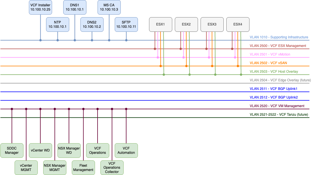
All the FQDNs mentioned below must exist in your DNS before you deploy VCF.
| Component | IP ADDRESS | FQDN | Description |
|---|---|---|---|
| VCF Operations | 10.250.20.51 | vcf9-md01-vrops01a.blanketvm.com | VCF Operations Analytics node. |
| VCF Operations Collector | 10.250.20.55 | vcf9-md01-fleet.blanketvm.com | VCF Operations collector. |
| Fleet Management | 10.250.20.10 | vcf9-md01-vrops01cp01.blanketvm.com | Fleet Management. |
| VCF Automation VIP | 10.250.20.100 | vcf9-md01-vra01.blanketvm.com | VCF Automation. |
| VCF Automation Node IP1 | 10.250.20.101 | – | VCF Automation Node IP. |
| VCF Automation Node IP2 | 10.250.20.102 | – | VCF Automation Node IP for failover. |
| vCenter Server | 10.250.20.1 | vcf9-md01-vcenter01.blanketvm.com | vCenter MGMT. |
| NSX Manager VIP | 10.250.20.30 | vcf9-md01-nsx01.blanketvm.com | NSX Cluster VIP. |
| NSX Manager Node IP | 10.250.20.31 | vcf9-md01-nsx01a.blanketvm.com | NSX Manager first node. |
| SDDC Manager | 10.250.20.11 | vcf9-md01-sddc.blanketvm.com | SDDC Manager. |
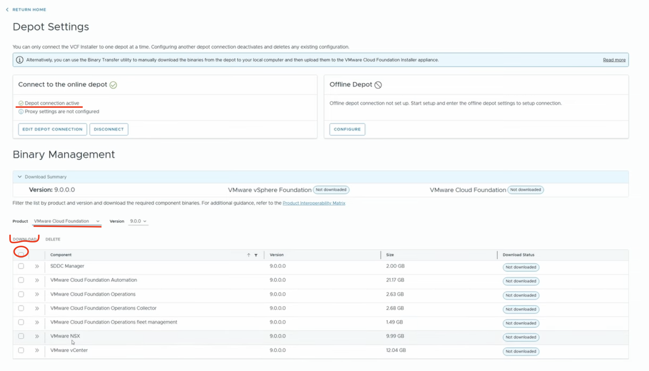
VCF 9 Online Depot Configuration:
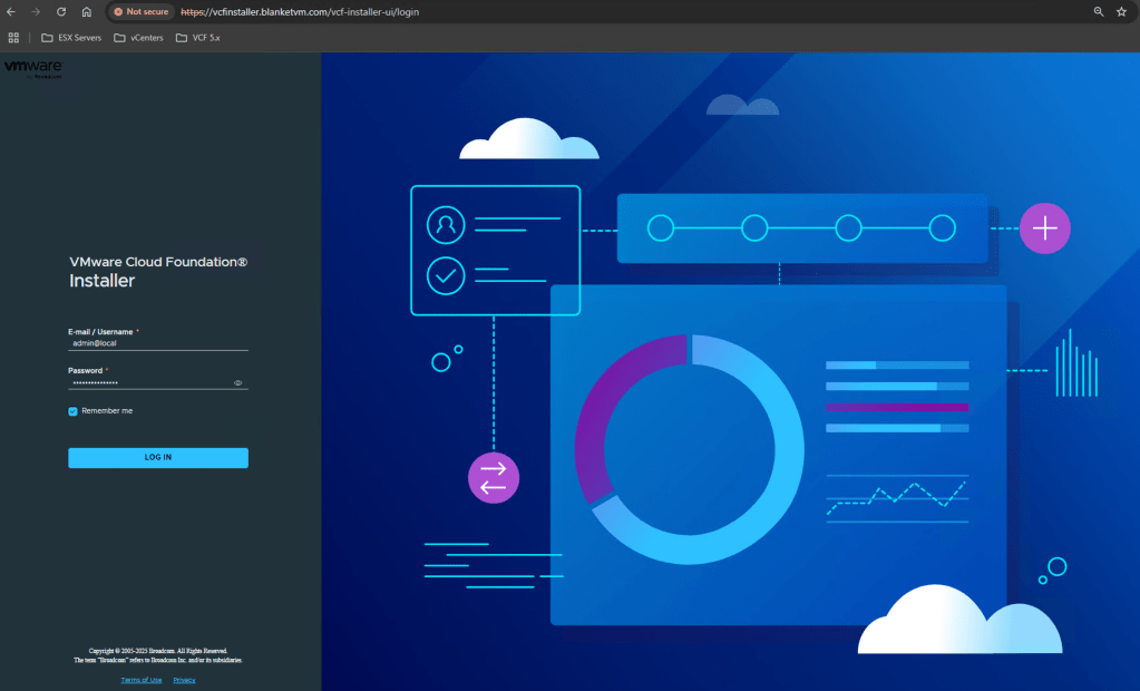
- Log in to the VCF Installer that was deployed in the first part using the user:
admin@local. In my case, it is https://vcfinstaller.blanketvm.com.
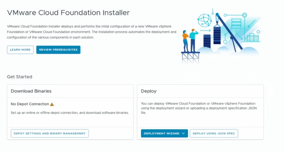
- Click on
Depot Settings and Binary Managementand configure the Online Depot.
NOTE: To download VCF Binaries, you need to have a Download Token. How to receive it, you can find here:
https://knowledge.broadcom.com/external/article/390098
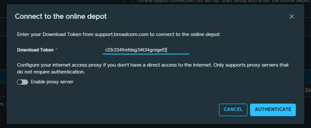
- Download all Binaries required for VCF 9.

VCF 9 Deployment:
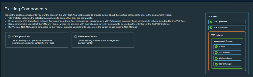
- Go to the main page and start the deployment Wizard.
- On the Existing Components page leave both check boxes unselected. It is a completely new deployment and we do not have existing components.
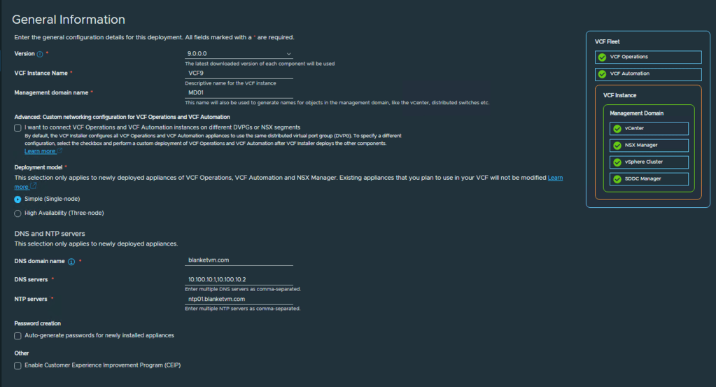
- On the General Information page, we need to fill in the following information:
– VCF Instance Name: up to you, I used VCF9
– Management Domain Name: MD01 or choose yours.
– Advanced Custom Networking: I use a simple networking approach where all components are placed in the same port group. If you want to separate VCF Operations and VCF Automation into different segments, use that checkbox.
– Deployment Model: I useSimplebecause of the resources, but if you want to deploy NSX, VCF Operations, and VCF Automation as a multinode deployment, useHigh Availabilitymode.
– DNS and NTP configuration: type your domain name and DNS, NTP Servers as a comma-separated value.
– Auto-generate passwords: Check this if you want to have passwords generated by VCF Installer. You will be able to see passwords at the end of the wizard.
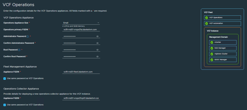
- On the VCF Operations page, choose your configuration:
– Operations Appliance Size: depends on the number of objects and metrics you will have. Check sizing guide:
https://knowledge.broadcom.com/external/article?articleNumber=397782
vROPS Sizer: https://vropssizer.broadcom.com/
– FQDNs: type FQDNs for Operations Primary node, Fleet Management appliance and Operations Collector appliance
– Passwords: use this checkbox if you want to use the same password for each appliance.
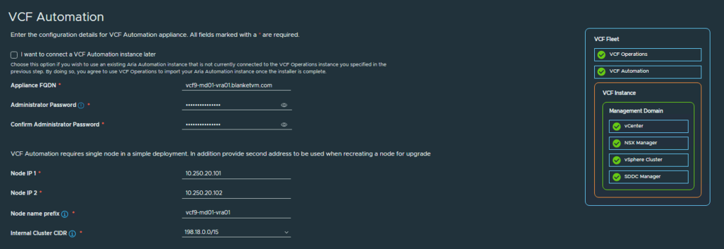
- On the VCF Automation tab, choose configuration for the Automation component.
– FQDN: Domain name that will be used to connect VCF Automation.
– Node 1 IP: IP address that will be used during deployment for the node.
– Node 2 IP: IP address that will be used in case of node failure to redeploy a new node.
– Node name prefix: The prefix will be used for creating VM names.
– Internal Cluster CIDR: Use a CIDR that does not overlap with those used in your organization.
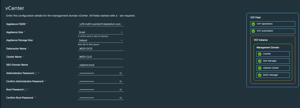
- The vCenter page requires information about vCenter and the SSO domain.
– Appliance FQDN: must exist in DNS.
– Size: depends on your needs. Please refer to the sizing guide.
– Datacenter name: name of the datacenter object in the vCenter Server.
– Cluster name: name of the management cluster object in the vCenter Server.
– SSO Domain name: typicallyvsphere.local, but you can set your own name.
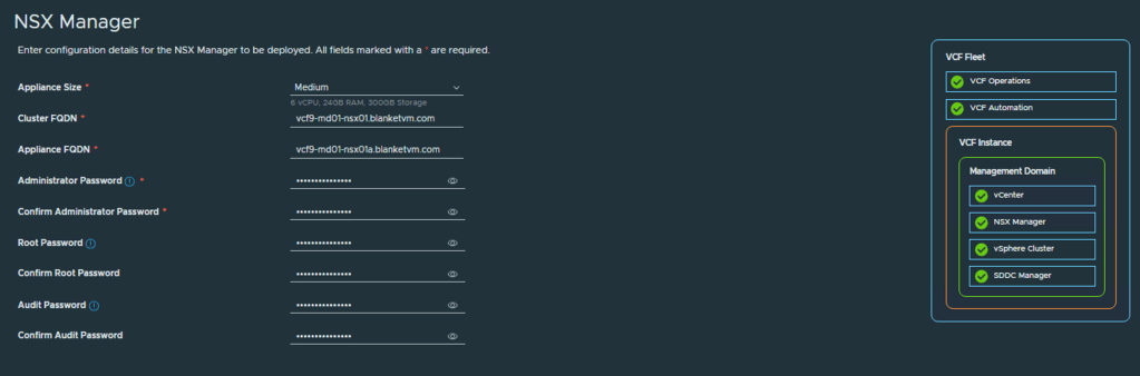
- The next page is about NSX Manager configuration:
– Appliance Size: I recommend using at least a medium-sized appliance.
– Cluster FQDN: VIP FQDN, prepared if you will use the cluster in the future.
– Appliance FQDN: FQDN of the first node.
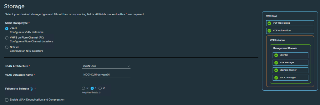
- Storage configuration.
VCF 9 allows you to configure 3 types of storage for the Management Domain as a primary storage: vSAN, VMFS on FC, and NFS v3. I use vSAN with OSA Architecture.
- ESX hosts configuration.
Type password (it must be the same for all hosts) and add at least 3 ESX Hosts to the list. Confirm Fingerprints.

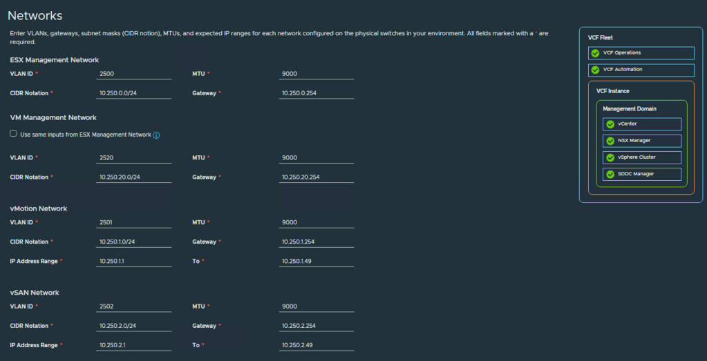
- On the Network page, configure subnets for ESX, VM Management, vMotion, and vSAN if you choose vSAN Storage.
In my case, I use 9000 MTU for all VLANs, but you can leave the default values if you want. Jumbo Frames are recommended for vSAN and vMotion.
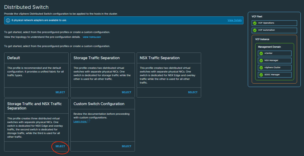
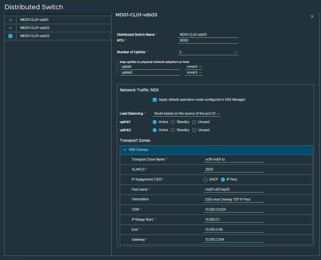
- The Distributed Switch configuration page enables you to select different vDS architectures based on the number of network adapters you have and the desired traffic distribution between them. In my case, I use six network adapters, and I want to separate vSAN traffic, NSX traffic, and vMotion traffic to three different switches. Adjust the selection to your needs.
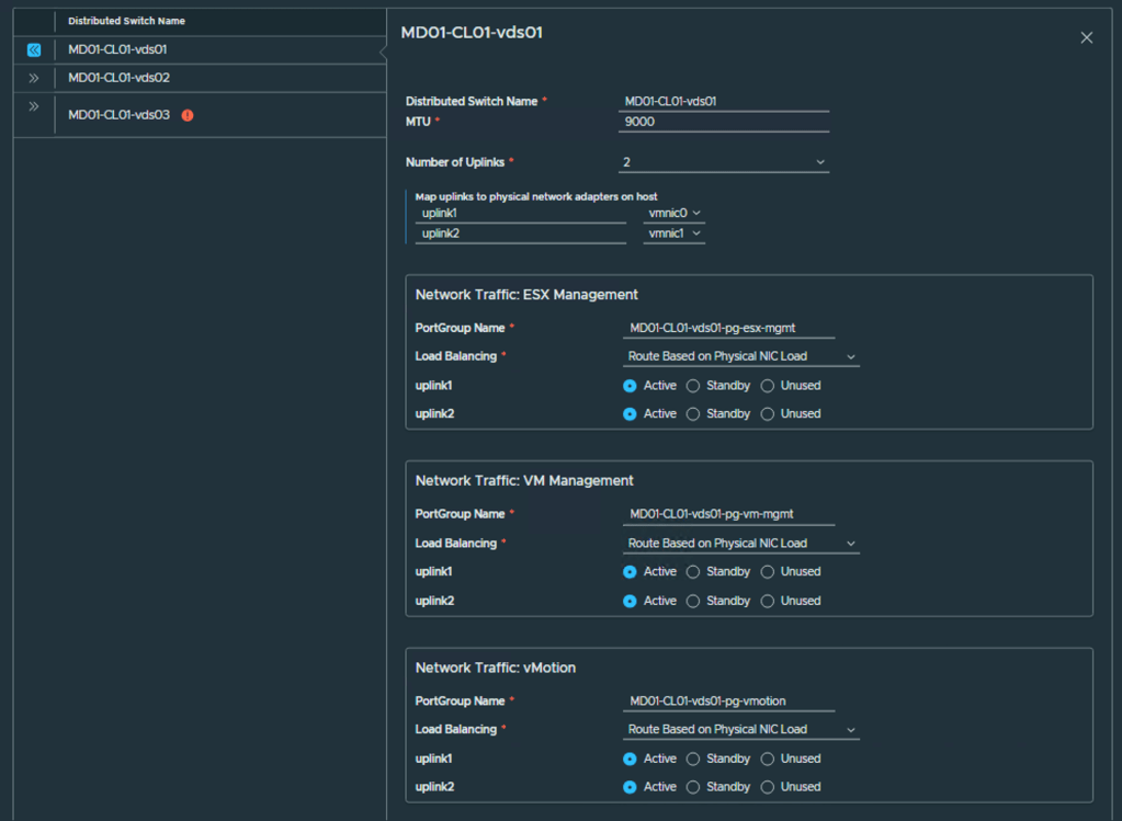
- You can configure all Distributed Switches as you need. My example below.
VDS01 is used for ESX and VM Management traffic, as well as vMotion.
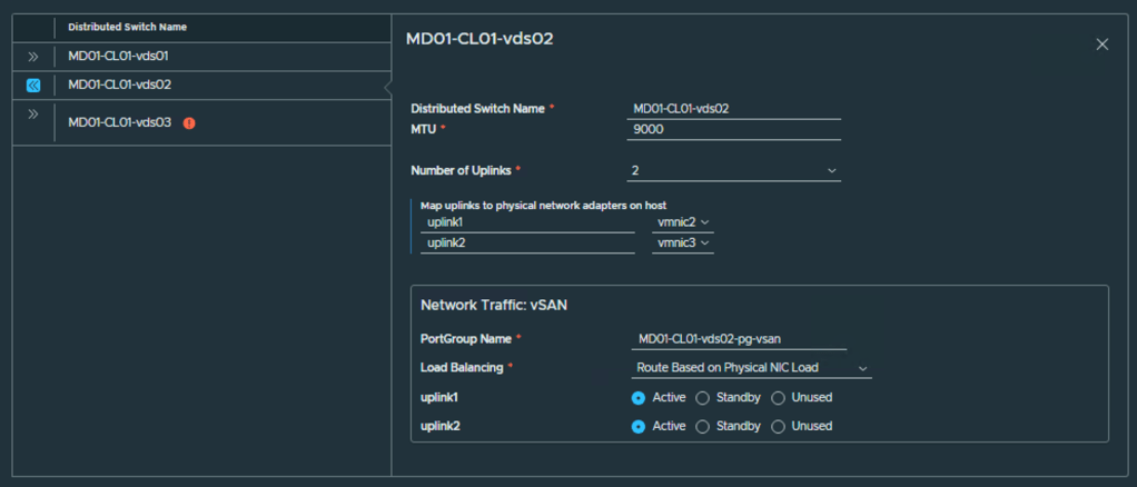
VDS02 is used for vSAN traffic.
VDS03 is an NSX switch for Overlay.
You can change VMNIC selection, Uplink configuration, VDS name, and Load Balancing policy.
For the NSX switch, you need to provide the Overlay configuration:
– Transport Zone Name: name of transport zone.
– VLAN ID: VLAN for Host Overlay.
– IP Assignment: How you want to assign IP addresses to TEP (DHCP or IP Pool).
– Pool name: Name for IP Pool.
– CIDR: subnet for selected VLAN.
– IP Range Start and End IP: IP Pool for TEP.
– Gateway: Provide a gateway for the selected subnet.
- SDDC Configuration page. Provide FQDN and passwords for SDDC Manager.
NOTE: If you installed VCF Installer on the first node in the Management Domain, it becomes an SDDC Manager. If it is outside VCF, a new SDDC Appliance will be deployed.

- Review the Summary page and proceed to the Validation section.
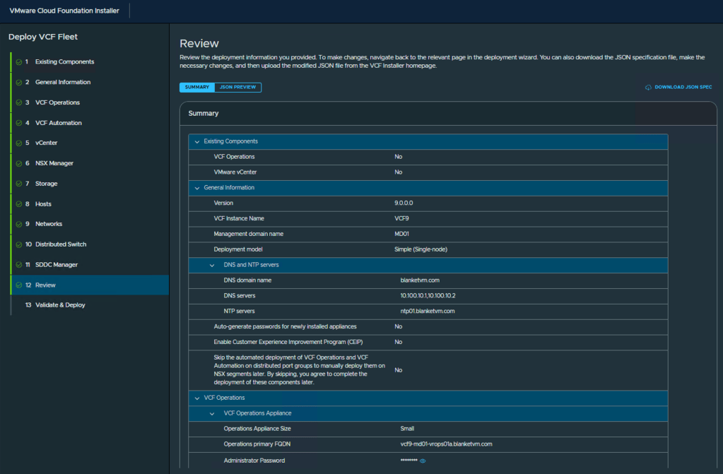
- Check all validations and click Deploy. Then wait a few hours 🙂

NOTE: One crucial thing. VCF Automation VM requires XX vCPU. ESX Hosts in my lab have only 14 cores, so it is not possible to power on such a VM! Of course, you should use hardware compatible with the requirements, but I do not have such. Before powering on the VCF Automation VM, I changed the VM configuration and reduced the vCPU to 14. And VCF Installer can power it on.
- And success!

Conclusion:
In this post, we walked through the VCF 9 bring-up process using VCF Installer, including validation of the deployment parameters, automated deployment of core components, and successful handover to the VCF Instance. A successful bring-up marks a significant milestone, laying the foundation for managing your Software-Defined Data Center with confidence and consistency.
In the next part of this series, we’ll explore post-bring-up tasks such as license management, user configuration, and preparing for workload domain deployments. Stay tuned!

8 thoughts on “VCF 9 Deployment PART2: VCF deployment.”